
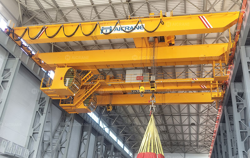
Specifying a 40-ton overhead crane is a critical engineering and capital expenditure decision. At this capacity, a crane is no longer a simple, stand-alone piece of material handling machinery; it is a major structural system that dynamically couples with the building itself.
A common and highly costly mistake in industrial facility design or brownfield retrofitting is treating crane procurement and building design as isolated variables. In reality, the physical dimensions of your facility dictate the crane’s configuration, while the required lifting envelopes and wheel loads of the crane dictate the building’s structural design. Failing to align these parameters in the early planning phases results in lost floor coverage, expensive structural remediation, or a crane that must be derated to operate safely.
1. Defining the Building Envelope: The Core Spatial Dimensions
Before drafting a 40 ton overhead crane technical specification, project managers must establish the baseline dimensions of the building’s interior envelope. Four primary measurements define the physical boundaries for the crane designer:
1.1 Span (S)
The span is the center-to-center distance between the runway rails. For a 40-ton crane, the span directly determines the depth, weight, and profile of the bridge girders.
- Structural Impact: Because a 40-ton live load exerts massive bending moments, longer spans require deeper steel plate girders or box girders to control deflection. This deflection is typically restricted to a strict ratio, such as L/800 or L/1000 of the span under CMAA Class D or equivalent international standards.
- Dead Weight Cascades: Deeper girders inherently increase the dead weight of the crane. This dead weight requires larger drive motors, heavier end trucks, and ultimately adds to the load transmitted to the building’s columns.
1.2 Runway Elevation (Height Under Boom / HUB)
This is the vertical distance from the finished floor level (FFL) to the top of the runway rail. It serves as the baseline vertical marker from which the crane’s hoist limits and total lift are calculated.
1.3 Clear Overhead Height
The vertical distance from the top of the runway rail to the lowest obstruction on the roof structure—such as roof trusses, rafters, purlins, fire suppression piping, or lighting fixtures. This space must house the crane’s bridge girders, the top-running trolley assembly, and the mandatory air-gap safety clearances.
1.4 Runway Length and Power Distribution
The total longitudinal distance the crane travels along the bay. This determines the length of the runway beams and the specification of the conductor bar (electrification system). For a 40-ton crane, voltage drop calculations over long runway lengths are critical; multi-point power feeds or larger copper-clad conductor bars may be required to prevent motor stalls during peak acceleration.
2. Vertical Clearances: Balancing Effective Lift and Headroom
In heavy industrial operations, maximizing the effective lift (the actual vertical travel distance of the hook) is usually the primary operational goal. However, a 40-ton hoist mechanism requires a significant physical footprint. The hoist drum, wire rope, gearbox, motor, and bottom block require substantial vertical space.
2.1 The Headroom Challenge
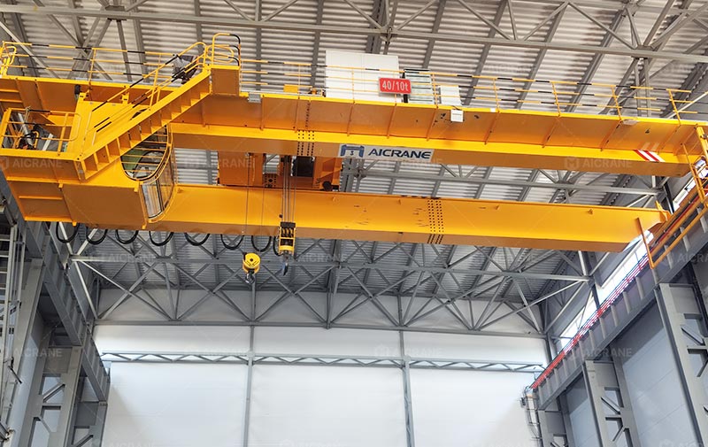
Headroom refers to the vertical distance from the saddle of the hook (at its highest position) to the highest point of the crane assembly. For a standard 40-ton top-running double girder overhead crane, this headroom dimension typically ranges from 1500 mm to 2000 mm (5 ft to 6.5 ft).
If the clear overhead height of your building is constrained, a standard crane configuration will force your highest hook position downward, compressing your effective lifting window. For example, if you must lift a 4 m tall assembly out of a machining center and clear a 3 m high safety enclosure, the required hook height is at least 7 m. If the building’s low clearances push the upper hook limit down to 6.5 m, the production line will be rendered inoperable.
2.2 Engineering Solutions for Low-Headroom Facilities
When building vertical dimensions are non-negotiable, crane engineers can deploy specific design configurations:
- Top-Running Double-Girder Configuration: This is the industry standard for 40-ton applications. By running the trolley on rails mounted to the top of the bridge girders, the hoist mechanism can sit between the girders rather than below them. This design salvages significant vertical clearance.
- Low-Headroom Trolley Assemblies: The hoist can be side-mounted or staggered on the trolley frame. This lowers the highest mechanical point of the trolley but can introduce asymmetrical wheel loads on the bridge rails, requiring careful balancing and girder stiffening.
3. Horizontal Clearances: Hook Approaches and Spatial Dead Zones
A 40-ton crane cannot service the entire floor area of a bay. Structural boundaries, bumpers, and the physical width of the crane’s components prevent the hook from reaching the walls. Identifying these dead zones is essential for logical machinery and workflow layouts.
3.1 Side Hook Approach (Left and Right Limits)
The side approach is the minimum horizontal distance between the centerline of the runway rail and the centerline of the hook when the trolley is positioned at its furthest lateral limit.
- Mechanical Drivers: A 40-ton hoist features heavy steel side plates, safety bumpers, and end stops. These physical components prevent the trolley from traveling to the absolute edge of the bridge.
- Operational Impact: The side approach for a crane of this class is typically between 1000 mm and 1400 mm (3.2 ft to 4.6 ft). Consequently, a strip of floor space along both walls of the bay remains inaccessible to the primary hook. Heavy machinery, storage racks, or material feed stations must be positioned outside of these horizontal dead zones.
3.2 End Hook Approach (Longitudinal Limits)
Similarly, the end approach is the distance between the centerline of the hook and the physical end of the runway beam.
- Mechanical Drivers: To distribute the massive load of a 40-ton payload plus the crane’s self-weight, the crane requires long end trucks. These end trucks are typically equipped with four or eight wheels, depending on the building’s runway capacity.
- Operational Impact: These long end trucks, combined with heavy-duty hydraulic or polyurethane bumpers, prevent the bridge from getting close to the end walls. The typical end hook approach ranges from 1500 mm to 2500 mm (5 ft to 8.2 ft), which must be accounted for in the facility’s longitudinal logistics flow.
4. Structural Interaction: Wheel Loads, Wheelbase, and Rigidity
A 40-ton rated crane does not apply only 40 tons of load to the building structure. The total load includes the live load plus the dead weight of the trolley, hoist, bridge girders, and accessories. This combined weight can easily reach 65 to 75 tons of total force.
4.1 Maximum Wheel Load Calculation and Distribution
When the trolley carries its rated 40-ton load and travels to the extreme end of the bridge, it concentrates the maximum possible force onto one runway.
Total Dynamic Load = (Payload + Trolley Weight) * Impact Factor + Bridge Weight Contribution
This concentrated force is distributed across the wheels of the end truck. To prevent these localized forces from crushing the runway rails, buckling the runway beams, or damaging the column corbels (brackets), the overhead crane manufacturer must optimize the wheelbase (the distance between the end truck wheels).
- Wide Wheelbase: Spreading the wheels farther apart distributes the maximum wheel load over a longer section of the runway beam, reducing localized bending stresses.
- Engineering Trade-off: Increasing the wheelbase directly increases the longitudinal end hook approach, thereby expanding the dead zones at both ends of the building.
4.2 Runway Alignment and Structural Rigidity
Runways are rarely perfectly straight. However, CMAA Specification 70 and ISO 12488-1 dictate highly stringent installation tolerances. For a 40-ton crane, if the runway span or elevation varies beyond the millimeter-level tolerances over the length of the bay, the crane will suffer from “skewing” or “binding.” This introduces severe horizontal forces into the building’s columns, causing rapid wheel flange wear, rail degradation, and structural fatigue.
5. Technical Specification Checklist for Project Managers
When preparing your Request for Proposal (RFP) or engineering specification for a 40-ton overhead crane, ensure the following dimensional parameters are explicitly defined:
| Parameter | Operational Impact | Technical Target / Requirement |
|---|---|---|
| Top Safety Clearance | Prevents structural collision during building deflection or seismic drift. | Maintain a minimum vertical gap of >= 100 mm (~4 in) between the crane’s highest point and the lowest roof obstruction. |
| Headroom Limit | Maximizes vertical lifting range in constrained spaces. | Specify maximum allowable height from hook saddle (upper limit) to crane high point (H <= 1800 mm recommended). |
| Side Hook Approach | Dictates placement of heavy machinery relative to walls. | Restrict lateral limits (C_left, C_right <= 1200 mm) to minimize floor space dead zones. |
| End Hook Approach | Impacts the handling of materials near end walls. | Limit end truck wheelbase and bumper lengths to keep end approaches within acceptable longitudinal limits. |
| Max Wheel Load Limits | Prevents structural failure of existing runway structures. | Define maximum allowable wheel load based on existing building column and corbel capacity (e.g., P_max <= 180 kN). |
| Runway Span Tolerance | Prevents crane binding, rail wear, and lateral column strain. | Limit runway span variation to within +/- 5 mm over the entire run. |
Conclusion
Specifying a 40-ton overhead crane requires a holistic understanding of structural engineering and spatial geometry. By precisely mapping your building’s vertical and horizontal clearances and analyzing how parameters like headroom, wheel spacing, and hook approach interact, you can prevent costly field modifications. Ensuring these clear physical boundaries are engineered into your overhead crane specification is the foundation of a safe, efficient, and long-lasting heavy-lift installation.